Page 1 of 2 12 LastLast
Results 1 to 20 of 30

Thread: Boost Leak

  1. #1

    Offline
     
    Name
    Jay
    Join Date
    Jan 2011
    Last Online
    03-05-2015
    Posts
    613
    Country
    United Kingdom
    Location
    Armagh/Dublin
    Car
    98 Legnum VR4
     

    Boost Leak

    Can someone tell me where the boost pipe on the bottom ic piping under the intake side should go to? had my car at a mechanics other day to fix my boost leak and he seems to have block this pipe up with a bolt.
    1998 Legnum VR4 Twin Turbo

    17" Evo VII alloys in black
    Comma 5.1 brake fluid
    Full exhaust system with decat
    Magnecor performance ignition leads
    NGK BKR7EIX plugs
    Blitz Boost controller Low: 0.5 bar High: 0.9 bar
    Turbo timer
    3 pillar pod with Boost, Oil temp & Psi gauges

  2. #2
    kiteman's Avatar

    Offline
     
    Name
    tommie
    Join Date
    Aug 2007
    Last Online
    26-09-2023
    Posts
    2,722
    Country
    Ireland
    Location
    kildare
    Car
    legnum 1997
     
    Jay, if you put up a photo of it, someone on here will be able to help.
    old age and treachery will outdo youth and skill anyday

  3. #3

    Offline
     
    Name
    Jay
    Join Date
    Jan 2011
    Last Online
    03-05-2015
    Posts
    613
    Country
    United Kingdom
    Location
    Armagh/Dublin
    Car
    98 Legnum VR4
     
    Will try get one in the morning then, if you remove the ic piping going to the inlet mani, its the ic piping under it that goes to the turbo, it has a boost pipe coming from it just near the rear of the engine if that helps

  4. #4
    Davezj's Avatar

    Offline
     
    Name
    Dave
    Join Date
    Jan 2006
    Last Online
    Today
    Membership ID
    255
    Posts
    16,248
    Country
    England
    Location
    Manchester
    Car
    VR-4
    My Garage
    Visit
     
    it sounds like the pipe that goes to the power steering valve. the flex pipe goes to the metal pipe the runs across the top of the engine and out the other side and on to the valve in to of the power steering pump. but you will not see the metal pipe if you have you engine cover fitted.

    and you are getting mixed up with you intercooler pipe terminology, the only intercooler pipe there is one that come directly from the intercooler to the throttle body, the rest of the pipework in that area is inlet pipe work and is low pressure stuff as it is all before the inlet to the turbos.

    Bye for Now!

  5. #5
    apeman69's Avatar

    Offline
     
    Name
    Alan
    Join Date
    Jan 2008
    Last Online
    24-06-2023
    Posts
    1,596
    Country
    Wales
    Location
    Torfaen, South
    Car
    VR-4 Leg & R33
     
    Quote Originally Posted by jjayokocha View Post
    Can someone tell me where the boost pipe on the bottom ic piping under the intake side should go to? had my car at a mechanics other day to fix my boost leak and he seems to have block this pipe up with a bolt.
    Sounds like you might mean the thick black rippled rubber pipe underneath the air box/air filter. If so then it's pipe number 1 in the doodle below.
    This may not be applicable if you have a boost controller fitted that does not use the standard boost solenoid as pipe number 1 is the outlet from the solenoid that is used to bleed air back to the air intake.

    boost pipes again 2.jpg

    Here's the old favourite factory hosing diagram for further reference:-

    Boosthosingdiagram.jpg
    Last edited by apeman69; 16-08-2011 at 02:16 PM.
    '97 Legnum VR-4 type S
    DONE - SARD 530cc injectors, SARD AFPR, FMIC, MAP2-ECU, Ralliart air filter & 'Special' MAF, Magnecor leads, NGK 7s, Polyeurethane engine mounts, New lash adjusters, RPW downpipes, Powerflow 3" full de-cat exhaust, Reconditioned turbos, Bespoke AYC gauge, SARD R2D2 BOV, CarPC with EvoScan, Fusion amp & InPhase sub, EBC Turbo grooved & dimpled brake discs, EBC red & green pads, HKS SuperForm Lowering springs, Hydraulic bonnet dampers, Momo steering wheel, Bespoke wideband AFR/Oil pressure gauge thingy, New wiper blades all round!, Amsoiled... woo hoo!
    Growling out 349ft/lb torque, 296 fly HP @ 0.9 bar

  6. #6

    Offline
     
    Name
    Jay
    Join Date
    Jan 2011
    Last Online
    03-05-2015
    Posts
    613
    Country
    United Kingdom
    Location
    Armagh/Dublin
    Car
    98 Legnum VR4
     
    Ye sorry if i make it confusing, it looks to be what you have in the pic as number one, my pipe that goes to throttle body has 2 pipes coming from it, one as u said goes in under the engine cover onto the fpr i think it is and the other goes to the boost solenoid.

    pipe number 1 wasnt conencted to anything, just a pipe coming from the thick black rippled pipe and had the end blocked off with a bolt.

  7. #7
    Nick Mann's Avatar

    Offline
     
    Name
    Nick
    Join Date
    Sep 2003
    Last Online
    20-04-2024
    Membership ID
    17
    Posts
    24,903
    Country
    United Kingdom
    Location
    Redditch
    Car
    Legnum type-S
    My Garage
    Visit
     
    The pipe from the ribbed pipework goes to the vent connection on the boost solenoid, as mentioned above. This is so that any air bled from the system by the boost solenoid stays in the inlet system between the MAF and the engine.

  8. #8

    Offline
     
    Name
    Jay
    Join Date
    Jan 2011
    Last Online
    03-05-2015
    Posts
    613
    Country
    United Kingdom
    Location
    Armagh/Dublin
    Car
    98 Legnum VR4
     
    Right well my pipes must be all over the place.

    1st pipe i have is what comes from the T-piece where the actuators meet, this goes to the boost solenoid (the one at the front and nipple closest to engine)
    2nd pipe comes from the 2nd nipple on the front solenoid and closet to the basttery which goes to one of the nipples on the ic piping going to the inlet mani.
    3rd pipe goes from ic piping to inlet mani to under the engine cover for the fpr
    4th pipe is in the one coming from thick black ripped pipe and is just plugged with a bolt at other end

    I know there is a few more pipes which i need to check in morning to see where they go like the solenoid at the rear.

  9. #9
    apeman69's Avatar

    Offline
     
    Name
    Alan
    Join Date
    Jan 2008
    Last Online
    24-06-2023
    Posts
    1,596
    Country
    Wales
    Location
    Torfaen, South
    Car
    VR-4 Leg & R33
     
    If you don't have a boost controller on there then the factory hosing diagram is the one to follow

    Sent from my Huge Brain using MyFingers

  10. #10

    Offline
     
    Name
    Jay
    Join Date
    Jan 2011
    Last Online
    03-05-2015
    Posts
    613
    Country
    United Kingdom
    Location
    Armagh/Dublin
    Car
    98 Legnum VR4
     
    I have an mbc fitted, i have the boost pipe coming from actuator tee into the bottom on the mbc and top of mbc goes into the piping that goes to throttle body. This is the way i got the car so presume the plonker that had it before me (not Trev on here) had made a mess of everything.

    Now there is 2 pipes that come from the black ripped piping under the tb piping. 1 is a thick black one that goes away into the engine and 2nd is a small pipe which is plugged with a bolt.

    Also the tb has a pipe coming from it at the front which goes down onto the rear solenoid closest to back of the engine.

    I tried going by the diagram there but confused myself and didnt fancy starting to replumb it all incase i made it worse.

  11. #11
    Davezj's Avatar

    Offline
     
    Name
    Dave
    Join Date
    Jan 2006
    Last Online
    Today
    Membership ID
    255
    Posts
    16,248
    Country
    England
    Location
    Manchester
    Car
    VR-4
    My Garage
    Visit
     
    As i said earlier the thick rippled black rubber pipe (about 2 inch diameter) under the pipe that is connected to the throttle body is not an intercooler pipe and does not contain boost pressure at any time.

    it will contain a small vacuum pressure when engine is in idle, and slightly bigger vacuum when the car is being driven as the air is succed in by the turbo's, but the pipe that small comes off that i believe goes to the power steering valve. and the bigger pipe i assume is the rocker cover breather pipe.

    the only big pipe (approx 3 inch diameter) that contains boost on that side of the engine bay is the one that goes to the throttle body from the intercooler.
    i think you are confusing everyone when you talk about the rippled pipe.

  12. #12
    apeman69's Avatar

    Offline
     
    Name
    Alan
    Join Date
    Jan 2008
    Last Online
    24-06-2023
    Posts
    1,596
    Country
    Wales
    Location
    Torfaen, South
    Car
    VR-4 Leg & R33
     
    Don't panic as it sounds like it's connected correctly.
    The only thing to consider about the rippled black pipe, when fitting an MBC, is plugging the thin vacuum tube which has already been done
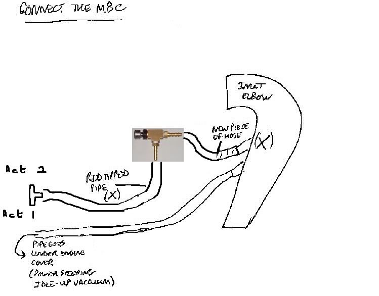
    Here's a couple of doodles I did ages ago which should give you a better idea of what needs to be connected where.
    This was for one of the in-cabin adjustable MBCs but whichever type you have should be in the same place piping-wise.
    With the MBC fitted you can disconnect the boost solenoid vacuum piping completely (simply by blocking off the pipes that go into and out of the solenoid: leave the electrical plug connected) so that the MBC is connected directly between the red-tipped pipe of the black plastic inlet elbow and the wastegate actuators.

    jjayokocha 1.jpg
    jjayokocha 2.jpg

  13. #13

    Offline
     
    Name
    Jay
    Join Date
    Jan 2011
    Last Online
    03-05-2015
    Posts
    613
    Country
    United Kingdom
    Location
    Armagh/Dublin
    Car
    98 Legnum VR4
     
    Cheers apeman for the diagram, now i am getting somewhere.

    In diagram 1 yes i have one pipe that goes to under the engine cover.

    The 2nd diagram i have an r spec mbc to which i have pipe going from actuator t piece straight into bottom of mbc and then pipe out back of mbc goes into the inlet elbow. I noticed in ur diagram though u have a t piece in which 1 line runs up to mbc & other goes straight into the inlet elbow. Maybe this is where mine is wrong.

    I will do my best in morning when i get into work to get some pics and highlight the other pipes that are under the inlet elbow as i have down there not conencted at 1 end.

  14. #14
    apeman69's Avatar

    Offline
     
    Name
    Alan
    Join Date
    Jan 2008
    Last Online
    24-06-2023
    Posts
    1,596
    Country
    Wales
    Location
    Torfaen, South
    Car
    VR-4 Leg & R33
     
    The drawings are for one of the turbosmart style mbcs that have a metal block t-piece that is part of the mbc. This then joins to the separate adjusting mechanism.
    If your mbc is a 1 piece L shaped jobby, for example, then it's connected in place of my metal t-piece. Hope this makes sense!

    Sent from my Huge Brain using MyFingers

  15. #15

    Offline
     
    Name
    Jay
    Join Date
    Jan 2011
    Last Online
    03-05-2015
    Posts
    613
    Country
    United Kingdom
    Location
    Armagh/Dublin
    Car
    98 Legnum VR4
     
    I did a bit of art work on ur diagram to show how i have my mbc set up, hope u don't mind. I bypassed the solenoid closet to the front of the car to set it up as from what i read on here. Hopefully it's set up correctly.


  16. #16
    Davezj's Avatar

    Offline
     
    Name
    Dave
    Join Date
    Jan 2006
    Last Online
    Today
    Membership ID
    255
    Posts
    16,248
    Country
    England
    Location
    Manchester
    Car
    VR-4
    My Garage
    Visit
     
    so you were not talking about the rippled pipe under the IC pipe that goes to the throttle body, you were talking about the very small pipe that has spiral wrap round it. if you had said that it would have saved a lot of confusion.

    but hey why should i worry about your issues, you seem to completely ignore me anyway. common curtsy cost nothing.
    i am not talking about you Alan.

  17. #17

    Offline
     
    Name
    Jay
    Join Date
    Jan 2011
    Last Online
    03-05-2015
    Posts
    613
    Country
    United Kingdom
    Location
    Armagh/Dublin
    Car
    98 Legnum VR4
     
    Apologies Dave, i was confusing myself with everything so started off with making sure the mbc was plumbed in correctly.

    Yes i do still have an issue with the ripped pipework under the inlet elbow. I have a small hose coming from it that is plugged at other end with a bolt, as i said best i can do is remove inlet elbow in the morning n try get some good pics. Just have a feeling the plonker before me just connected all hoses up together cause so far i found 3 t pieces!

  18. #18
    Kenneth's Avatar

    Offline
     
    Name
    Kenneth
    Join Date
    Nov 2004
    Last Online
    12-01-2024
    Membership ID
    NZ002
    Posts
    6,968
    Country
    New Zealand
    Location
    Cambridge
    Car
    Kia Sorento :P
    My Garage
    Visit
     
    I just looked at your diagram of your MBC setup.

    Be aware that the Red tipped hose usually has a restrictor in it. It is a piece of metal with a very small hole in it. This could case your MBC to be especially sensitive, or even to be impossible to adjust to a reasonable boost level.

  19. #19

    Offline
     
    Name
    Jay
    Join Date
    Jan 2011
    Last Online
    03-05-2015
    Posts
    613
    Country
    United Kingdom
    Location
    Armagh/Dublin
    Car
    98 Legnum VR4
     
    Kenneth thats where i run into problems, young lad had replaced all factory hoses with silicone ones. Only restrictor i have come across is the little one in the std boost solenoid nipple.

  20. #20
    apeman69's Avatar

    Offline
     
    Name
    Alan
    Join Date
    Jan 2008
    Last Online
    24-06-2023
    Posts
    1,596
    Country
    Wales
    Location
    Torfaen, South
    Car
    VR-4 Leg & R33
     
    Just to clarify: the std boost solenoid is attached to a metal bracket along with the fuel pressure solenoid. The boost solenoid is the one on the left as you look at it standing at front bumper. IIRC the fuel one is brown.
    If you have bypassed the boost sol by blocking off/removing the pipes then the pipe off the rippled thick air filter pipe (there's gotta be a proper name for this) DOES need to be plugged as it is one of the original connections of the boost solenoid. Leave the electrics plugged in.
    I'd make sure the connections to the power steering idle up thingy and the fuel pressure sol are correct while you're at it.

    Dave, take a pill... and I DO mean you

    Sent from my Huge Brain using MyFingers

Page 1 of 2 12 LastLast

Similar Threads

  1. boost leak?
    By Wobble in forum General / Questions
    Replies: 17
    Last Post: 06-05-2011, 12:57 PM
  2. boost leak tester
    By CARMEL120 in forum UK Chat
    Replies: 4
    Last Post: 12-09-2010, 10:16 PM
  3. thought i had boost leak
    By Paul C in forum General / Questions
    Replies: 0
    Last Post: 10-07-2007, 07:43 PM
  4. Boost Leak??
    By michaeli in forum General / Questions
    Replies: 3
    Last Post: 21-08-2005, 10:29 PM
  5. Boost Leak
    By enigma in forum UK Chat
    Replies: 38
    Last Post: 04-07-2005, 12:11 AM

Posting Permissions

  • You may not post new threads
  • You may not post replies
  • You may not post attachments
  • You may not edit your posts
  •